Please select Into the mobile phone version | Continue to access the computer ver.
Extension for OcuSync Camera to air unit?
11939 34 2018-8-16
Uploading and Loding Picture ...(0/1)
o(^-^)o
CraugWat
lvl.1

Offline

Is there an extension cable so I can place the camera further from the Air unit?  I'm setting up on a large fixed wing.  I want to mount the air unit inside the equipment bay and place the camera about two feet from the air unit.  It looks like USB C type cable and I can get extensions for that.  Hoever the camera cable is notched to match a tab on the air unit. So the DJI cable is polarized and will only fit one way.  USB C cables are not polarized.   I don't want to damage the camera or air unit by just experiementing!
Thanks
Craig
2018-8-16
Use props
Kryml Munsta
lvl.4
Flight distance : 185262 ft
  • >>>
Germany
Offline

+1
I was thinking about the same thing some days ago.

An extension-cable would be very helpfull
2018-8-16
Use props
fansee8d92ee
lvl.1

United States
Offline

I'd also like to know if this would work. I'm about to go buy a USB-C extension cable and try it myself, but I also worry about frying the unit. If I do try it I'll post here again with the results.
2018-8-22
Use props
CraugWat
lvl.1

Offline

fansee8d92ee Posted at 2018-8-22 06:59
I'd also like to know if this would work. I'm about to go buy a USB-C extension cable and try it myself, but I also worry about frying the unit. If I do try it I'll post here again with the results.

Did you try an extension cable?  Any luck?
2018-8-29
Use props
rogercaplan
lvl.1
United States
Offline

CraugWat Posted at 2018-8-29 06:19
Did you try an extension cable?  Any luck?

I just tried, no luck. I also tried one of these 90 degree adapters, didn't work either. I'll try with a thunderbolt 3 cable and report back.
2018-9-7
Use props
Bill-NM
lvl.2
Offline

rogercaplan Posted at 2018-9-7 10:05
I just tried, no luck. I also tried one of these 90 degree adapters, didn't work either. I'll try with a thunderbolt 3 cable and report back.

Roger... Ever get anything to work?

Thanks.
2018-9-20
Use props
fansb1348b12
New
Turks and Caicos Islands
Offline

I'm looking at the same thing.  Bump
2019-3-3
Use props
Bill-NM
lvl.2
United States
Offline

Anyone find an extension cable yet?

Thanks...
2019-3-9
Use props
CSWHITING63
lvl.1

United States
Offline

Im looking for it too
2019-4-29
Use props
CSWHITING63
lvl.1

United States
Offline

Any luck on it
2019-4-29
Use props
Fardenco
New

Offline

Did anyone get anything working ? I'm also looking for extending this camera wire, it's really too short
2019-10-3
Use props
Biisbah
lvl.2
Flight distance : 5811358 ft
  • >>>
Finland
Offline

Has anyone found any method to extend the cable? Stock 10 cm cable is useless. I need at least 30 cm extension for proper installation.. Why DJI is not selling extensions?
2020-1-14
Use props
hsgreer
lvl.1

United States
Offline

Did anyone find a camera extension cable?
2020-3-15
Use props
xrk
lvl.2
Germany
Offline

I also wanted to extend the cable in order to put the camera next to GoPro on my FeiyuTech MiNi 3D Pro gimbal and stumbled upon this thread. As apparently there is no commercially available product, need to come up with own solution, so took the camera apart to look at the cable and it's wiring. The camera seems to be using I-PEX CABLINE-CA plug/socket https://www.i-pex.com/product/cabline-ca with 0.4mm pitch and 20 pins. The OcySync Air camera cable seems to use 19 micro-coax cables https://www.i-pex.com/products/micro-coax-discrete-wire.
This differs from normal USB-C 3.1 cables that use a different build with 8 mini-coax lines and additional shielded twisted wires and power lines, which is likely the reason it won't work with standard USB-C cable extensions. See this thread for more info: https://twitter.com/tubetimeus/status/1125929569398116352
My goal is now to create a custom cable with 19 micro-coax wires and more length than the original DJI OcuSync cable, which should work in case the signal attenuation remains not too high due to longer lines.


2020-9-2
Use props
CraugWat
lvl.1

United States
Offline

Nice job on the tear down and thanks for the pictures and identify the cables!  Keep us updated on your progress.  
2020-9-2
Use props
xrk
lvl.2
Germany
Offline

Minor update. Got myself a USB-C female breakout board for testing purposes:


When plugged with the notched side of the DJI custom USB-C plug towards the A-side pins,


here is the pinout of the I-PEX CABLINE-CA 20-pin plug to USB-C plug:
Pin 1 - B2 (white)
Pin 2 - B3 (white)
Pin 3 - B6 (black)
Pin 4 - B7 (green)
Pin 5 - B11 (blue, does not seem to carry any signal, 0V)
Pin 6 - B10 (yellow, does not seem to carry any signal, 0V)
Pin 7 - A2 (white, does not seem to carry any signal, 0V)
Pin 8 - A3 (white, does not seem to carry any signal, 0V)
Pin 9 - A11 (white)
Pin 10 - A10 (black)
Pin 11 - A7 (yellow, short 400 kHz pulses every roughly 16 ms)
Pin 12 - A8 (gray)
Pin 13 - A5 (blue, 2.7 V DC, except briefly after startup, where there is a signal with roughly 380 kHz)
Pin 14 - A6 (green, 2.7 V DC)
Pin 15 - B5 (black, does not seem to carry any signal, 0V)
Pin 16 - B8 (green, does not seem to carry any signal, 0V)
Pin 17 - not connected
Pin 18 - A4 (yellow, 1.8 V DC, not connected to B9)
Pin 19 - B9 (blue, 1.9V DC, not connected to A4)
Pin 20 - B4 and A9 (red, thicker than the other wires, carries 3.7 V DC)
Shield - B1, A12

(Note that A1 and B12 are not connected on the USB-C connector)


From the 19 wires, 18 seem to be AWG 40 micro-coax, so I am thinking of using Alpha Wire 9440 for custom extended cable:
https://www.alphawire.com/Products/cable/alpha-essentials/coaxial-cable/9440

The pin 20 wire, likely carrying a positive power supply, seems to be a little thicker as the other 18 wires, as can be seen from this image:
2020-09-20 10.32.37 OcuSync Air Unit camera wires.jpg

Stripping the micro-coax cable is somewhat tricky. Either one needs a machine like this:
https://www.schleuniger.com/en/products/strip/coax-stripping/coaxstrip-5300-rx/
(video demonstration of it: )
or one needs some lasers:
https://www.laserwiresolutions.com/applications/data-cable-stripping/micro-coax-cable/

I am thinking of constructing a custom tool out of 4 razor blades, something to look at the end like the this tool:
https://www.jokari.de/en/Top-Coax-Plus-2.htm

2020-9-19
Use props
xrk
lvl.2
Germany
Offline

I made some further progress. I built a short extension test unit using one female and one male USB-C breakout board and connected them with roughly 10 cm of ribbon cable. I soldered a 0.1" pitch double row pinheader in-between in order to be able to easily hook scope probes and observe the signals during Ocusync camera operation.
2020-10-18 15.31.27 Ocusync camera extension and probe.jpg

2020-10-18 16.53.45 measuring signals.jpg

2020-10-18 16.53.56 signal measurement.jpg

I was surprised to learn that the Ocusync unit still continued to work with that contraption in between, as the ribbon cable must be one of the worst choices for high-speed signals.
Even, with the 1m scope cable hanging on the wires, the image transmission continued to work without any problems (I tested with the scope all the pins).
Surely this sort of an extension must create significant amount of noise and as such is not what you want in your drone near other radio equipment that should work over longer range.

In order to minimize the effort with the labor intensive micro-coax cabling, I thought to look at the signal shapes in all the lines in order to use micro-coax only on lines carrying high-speed signal and normal wire on all other lines.

From Ocusync camera pin 5 (USB-C B11), 6 (B10), 7 (A2), 8 (A3), 15 (B5) and 16 (B8) I could only measure 0 V signal.
Here are the pins, where I could see a signal.
Pin 1 (B2, 2 images):

Pin 7 (1)

Pin 7 (1)

Pin 7 (2)

Pin 7 (2)

Note that the signal of pins 1 to 4, 9 and pin 10 all look very similar.

Pin 2 (B3, 2 images):

Pin 8 (1)

Pin 8 (1)

Pin 8 (2)

Pin 8 (2)


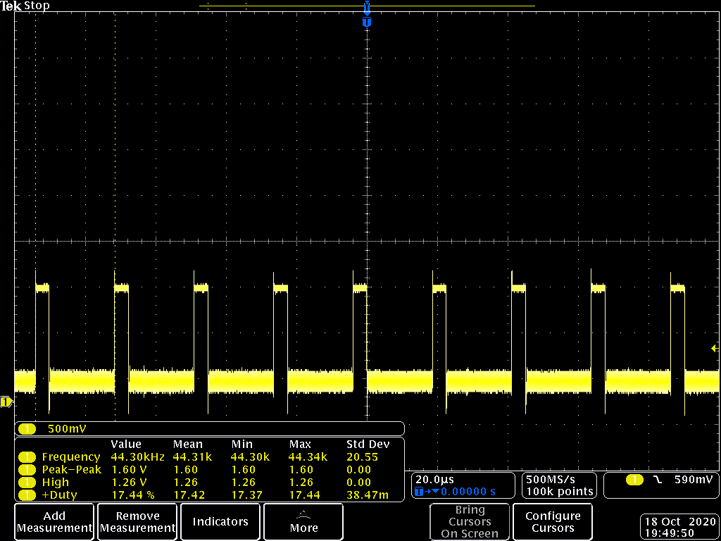
I plotted also both (Pin 1 and Pin 2 together and zoomed in heavily). Here are 8 images showing that the highest frequency component is roughly 30 MHz in these lines (also the highest I found across all lines looked at). Pin 1 (B2) is plotted in channel 1 in yellow, Pin 2 (B3) in channel 2 in cyan:
Ocusync camera pin 1 (B2, ch1) and pin 2 (B3, ch2) 01.png

another view:
Ocusync camera pin 1 (B2, ch1) and pin 2 (B3, ch2) 02.png
notice smaller chirps in Pin2/B3 signal.

Let's zoom in:
Ocusync camera pin 1 (B2, ch1) and pin 2 (B3, ch2) 03.png
another view:
Ocusync camera pin 1 (B2, ch1) and pin 2 (B3, ch2) 06.png

Zooming in even further:
Ocusync camera pin 1 (B2, ch1) and pin 2 (B3, ch2) 04.png
and more:
Ocusync camera pin 1 (B2, ch1) and pin 2 (B3, ch2) 05.png

Ocusync camera pin 1 (B2, ch1) and pin 2 (B3, ch2) 07.png

Ocusync camera pin 1 (B2, ch1) and pin 2 (B3, ch2) 08.png

Pin 3 (B6, 2 images):


Pin 4 (B7, 2 images):

Pin 11 (1)

Pin 11 (1)

Pin 11 (2)

Pin 11 (2)

Pin 9 (A11, 2 images, zoomed out and zoomed in):


Pin 10 (A10, 2 images):


Pin 11 (A7):


Pin 12 (A8, 3 images, not purely binary signal, has multiple levels):

Pin 16 (1)

Pin 16 (1)

Pin 16 (2)

Pin 16 (2)

Pin 16 (3)

Pin 16 (3)


Pin 13 (A5) - short pulses during startup with 376 kHz, then constant 2.7 V.
Pin 14 (USB-C A6): const 2.7 V
Pin 17 (not connected in camera to a cable)
Pin 18 (A4) constant voltage, roughly 1.8 V
Pin 19 (B9) constant voltage, roughly 1.9 V
Pin 20 (B4 & A9 are connected in camera), briefly after power-up comes up to constant 3.7V

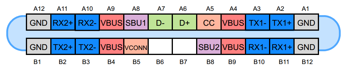
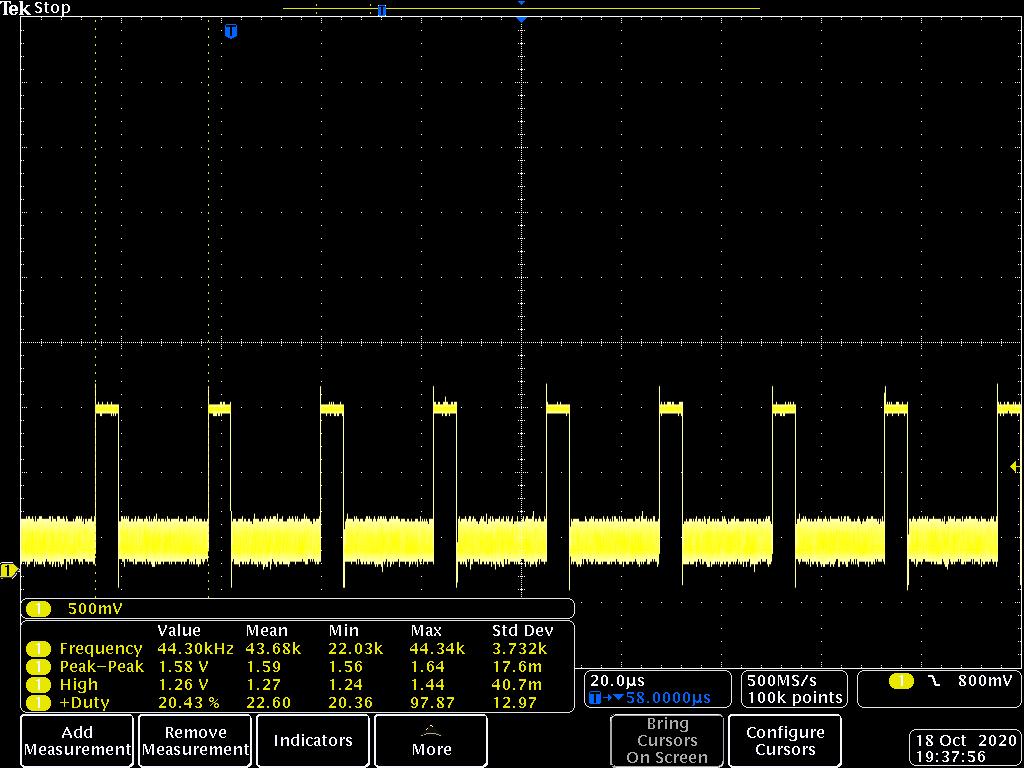
From the slightly longer than 16 ms frame that can be observed from the above scope screenshots, I take that the camera runs at 60 frames per second. We can also observe 44 kHz signal, which equates to roughly 720 lines @60Hz. All makes sense now. So the 30 MHz signal above, are likely the analog line scans of the camera sensor. I further assume the three pairs make up for red, green and blue channels.

If the maximum frequency across the wire is 30 MHz, the extension might not even need micro-coax, but might work with shielded data cable as well.

I wonder why lot of wires did not show any signals on my scope though. As DJI has spend an micro-coax cable for them in their wiring, they are likely not just for fun there. I might try to desolder in my ribbon cable contraption some of them to see if the camera still works on OcuSync unit after this.


Pin 4

Pin 4

Pin 5 (1)

Pin 5 (1)

Pin 5 (2)

Pin 5 (2)

Pin 6 (1)

Pin 6 (1)

Pin 6 (2)

Pin 6 (2)

Pin 14 (1)

Pin 14 (1)

Pin 14 (2)

Pin 14 (2)
2020-10-18
Use props
xrk
lvl.2
Germany
Offline

As the Ocusync camera continued to work nicely with two USB-C breakout boards and 10 cm of ribbon cable between, I thought I stretch this idea to see if it still works if I put 30 cm of ribbon cable in between. And the result - it sure does, the image comes up on the Goggles RE without any noticeable quality degradation:
2020-10-19 18.00.23 Ocusync with 30 cm ribbon cable still works.jpg

From the investigation results so far, the reason, why extending does not work with the standard USB-C extension cable, is IMHO that the A4 and B9 are typically shorted on USB-C, whereas on Ocusync they are separate lines.


2020-10-19
Use props
CraugWat
lvl.1

United States
Offline

xrk Posted at 10-19 08:07
As the Ocusync camera continued to work nicely with two USB-C breakout boards and 10 cm of ribbon cable between, I thought I stretch this idea to see if it still works if I put 30 cm of ribbon cable in between. And the result - it sure does, the image comes up on the Goggles RE without any noticeable quality degradation:
[view_image]

Again great work and investigation.  As you mentioned substituting ribbon cable for coax might not be a great idea in an RF sensitive environment.  Do you plan to investigate a coax solution?  Maybe we could get some people together and do a small run at a prototype cable house?
2020-10-19
Use props
xrk
lvl.2
Germany
Offline

> Do you plan to investigate a coax solution?

I am thinking of going with shielded thin & flexible data-wire instead of micro-coax, due to the effort required to strip and solder micro-coax.
Maybe a cable part from highly flexible USB 3.0 donor wire (plugs cut off to be resoldered according to Ocusync wiring) might work.


> Maybe we could get some  people together and do a small run at a prototype cable house?
Sounds like a good plan. Do you have contacts to such facility and can set this up to have a rough price estimate?

My goal is to have an extension that can be flexed a lot, as I plan to put the Ocusync camera on gimbal (next to Gopro), and the cable should handle constant movement. I wonder if the majority of interested parties will also need this, or would just be happy with semi-flexible/semi-rigid extension.


I have made further progress. An avid reader might have spotted in my previous posts the 6 wires that did not carry any signal according to my scope tests.
Well I went and desoldered them in my ribbon-cable-extension, and ahem... the camera still works.

Here's an image of my 10cm ribbon cable extension, 6 wires desoldered and heat-shrink caps added:
2020-10-19 18.50.58 desoldered 6 unused wires.jpg

Which means, A2, A3, B10, B11 and B5 and B8 are not used. I wonder why DJI chose to populate 6 micro-coax lines without actually using them. Were they meant possibly for future addition? 1080p camera version maybe? Who knows.

I prepared a diagram showing the Ocusync camera USB-C connector pinout relative to internal I-PEX CABLINE-CA plug:
Ocusync camera USB-C.png
2020-10-19
Use props
xrk
lvl.2
Germany
Offline

Here's a function diagram of my understanding of the Ocusync camera USB-C plug:

Ocusync camera USB-C functions.png

comparison with standard USB-C:


The video signals are pair-wise B2&B3, B6&B7, A10&A11, where one line of the pair is carrying the sync, and the other includes the sync as well, plus the video signal with 30 MHz bandwidth. I guess one pair is for red, other for green and the last for blue.

Likely, only these 3 pairs would need to be nicely shielded, e.g.  as the twisted pairs of the USB 3.0 cable:


Possibly, A8 that was carrying an analog signal as well, might also benefit from shield or being twisted with the GND line.

B4 & A9 carry the positive supply rail (+3.7V). B1 & A12 and the USB-C plug shield the negative rail (GND).
The wires carrying these should not be too thin in order not to induce too much voltage drop across the extension.


2020-10-19
Use props
xrk
lvl.2
Germany
Offline

I did want to give a try for micro-coax, and figured out a way to strip it manually.
The results are not perfect, but showing that this is indeed manually possible without having to rely on lasers or stripping machines.
I tried different tools and techniques and here are my findings.

I ended up using AVG #38 micro-coax, as with the smaller AWG #40 the success rate was significantly lower.

I considered first to build a DIY-tool for stripping, a self made semi-automatic stripping head using razor blades and servo motors, that would resemble the Schleuniger CoaxStrip 5400 machine in the video here:


But then I stumbled across Knipex 11 82 130 that according to specs can go down to 0.03 mm diameter, which is sufficient even for AWG #40 micro coax that has 0.09 mm diam. core conductor.

So went and purchased it to give it a go. After now playing with it an hour or so, I must say it works better than I initially expected.

The real trick is to first remove the outer jacket, then solder the shield, chemically remove the flux, and then first remove the shield by adjusting the Knipex pliers accordingly tighter (trial-and-error for the opening size). A further tightening the opening of the pliers is needed to remove the insulation to reveal the core. Here's the result (short circuit tested, no contact between the core and the shield):

2020-10-23 12.23.02 AWG38 micro-coax shield stripped.jpg

In the above big image (shot under a digital microscope), this does not look impressive, but it sure does in real-life. Notice that the background blue dot grid for size comparison has 0.1 mm grid!

In order to better grasp the miniature scale, here's an image of this stripped AWG #38 micro-coax next to a standard sized match tip:
2020-10-23 12.55.11 AWG38 micro-coax next to a match.jpg

In summary, contrary to my initial doubts, I think now that the micro-coax cabling is doable manually.

Next steps to create an extension cable for Ocusync camera, would be to develop and produce some PCBs for USB-C male & female side in order to attach the wires to the connectors.
I'll go with micro-coax for A5-A8,A10,A11,B2,B3,B6 and B7 and normal thin flexible wire for A4, B9 and a shared wire for A9&B4.
2020-10-23
Use props
xrk
lvl.2
Germany
Offline

I had access today to 6 GHz Tektronix spectrum analyzer, so went through all the pins of the Ocusync camera with it. This case now I did find signal peaks at 219 MHz and at 800 MHz, meaning micro-coax is likely the way to go at least for B2,B3,B6,B7,A7,A8,A10 and A11.

Here B2 (2 images):
2020-10-24 12.06.36 B2.png 2020-10-24 12.37.03 B2.png
A10:
2020-10-24 12.15.00 A10.png

A11:
2020-10-24 12.09.47 A11.png

I am a bit surprised to see such high frequency components in the signals.


2020-10-24
Use props
xrk
lvl.2
Germany
Offline

I created a PCB for the Ocusync extension cable. The PCB includes both sides of the USB-C in one PCB, to be cut in half after the delivery.

Here are two screenshots. First the top layer:


Top.png
and the bottom layer:

Bottom.png

The left side gets attached to the USB-C socket that connects to the Ocusync camera, the right side has USB-C plug and will be connected into Ocusync unit.
Between the PCB halves will go 9 AWG#38 micro coax cables plus 4 standard wires. I am planning with roughly 30 cm extension length.


I attach an Eagle CAD file to this post. I used OSHpark for the production (unbelievably low 1.40 USD only for the 0.8mm thick double sided PCB prototypes, incl. shipping to Germany) and am now waiting for the production and delivery (will take some weeks).

Ocusync_extension.zip

6.03 KB, Down times: 8

Eagle CAD Board file for Ocusync extension

2020-10-25
Use props
xrk
lvl.2
Germany
Offline

The PCBs from OSHpark arrived, so I can start the assembly.
Top_PCB.jpg Bottom_PCB.jpg
For starters I separated the PCB halves and soldered the USB-C connectors. Below you can see two images about this step. The USB-C receptacle, to connect with the OcuSync camera, can be seen on both images below on the left side and the male USB-C plug, to connect with the OcuSync Air Unit, is on both images on the right side:
Top_USB-C.jpg Bottom_USB-C.jpg
The notch of the Ocusync camera and the Ocusync unit should go both to the side where the USB-C receptable and plug have the cut in the outer shield (shown in the upper image above). Do note that although USB-C is reversible, the Ocusync cabling is not, as it is asymmetrically wired.

The cable between the USB-C receptable and the plug willl become 9 micro-coax cables (lines A5, A7, A8, A10, A11, B2, B3, B6 & B7), a single 0.25 mm² flexible wire for A9/B4 positive supply (red), and three thin 0.05 mm² flexible wires for A4 (yellow), A6 (green) and B9 (blue).

I started with the easiest, by soldering the 0.25 mm² and 0.05 mm² wires. As a first test, I soldered also a single Alpha-Wire AWG 38 micro-coax, shown in white in the pictures below:
USB-C female bottom side.jpg USB-C female top side.jpg
I am happy with the PCB design, this seems to work really nice with the USB-C connectors and also with the wires.

I continued with the micro-coax wires on the USB-C receptacle side. I have to say that my initial concerns with micro-coax were significantly lessend the more wires I successfully managed to strip and solder. I found the strategy to work best where I first strip the outer jacket (using Knipex 11 82 130 stripping tool):
01 stripping AWG 38 micro coax with Knipex 11 82 130.jpg 02 AWG 38 micro coax outer jacket stripped.jpg

Then spreading the shield, twisting it, tinning it and cutting it to length:
03 spreading the AWG 38 micro coax shield.jpg 04 tinning the AWG 38 micro coax shield.jpg
Finally stripping the isolator of the conductor and tinning the conductor and cutting it to length:
05 stripping AWG 38 micro coax insulation with Knipex 11 82 130.jpg 06 AWG 38 micro coax conductor tinned.jpg
After soldering all wires to the USB-C receptacle, this is the end result:
07 receptable side finished, top.jpg 08 receptable side finished, bottom.jpg 09 USB-C receptable side finished, top from side.jpg 10 USB-C receptable side finished, bottom from side.jpg
I did notice that the PCB can easily handle much thicker micro-coax than my chosen AWG 38 that is somewhat tedious to strip. If I would do this cable again, I would go with a little bit thicker micro-coax, such as AWG 34 that would make life much easier. Further benefit would be that the signal damping would be slightly less with a thicker micro-coax. The only downside I can think of is that the final cable would be tiny bit less flexible with thicker micro-coaxes.

The next step is to attach some protective outer layer for the wire bundle, mount the bend reliefs and connector caps, before continuing to solder the USB-C plug on the other side.
2020-11-21
Use props
xrk
lvl.2
Germany
Offline

I went for a 2 mm inner diameter cable braid to bundle the wires. Here is a picture of the present state with braid, bend reliefs (two tiny circular black rubber tubes over braid) and USB-C connector black plastic housings mounted:
OcuSync extension cable.jpg
I gotta say, I did not expect this step to be so time consuming, but getting all the thin wires through the braid, required me to solder all the wires together and attach this to a guiding solid wire, with what I was finally able to pull the bundle through the braid.
In the above image you will notice that the braid is somewhat compressed, this is to have temporarily good access to wire ends, in order to be able to solder them onto the USB-C plug in a next step. To be continued...
2020-11-22
Use props
CraugWat
lvl.1

United States
Offline

looking really good!  let us know how the last of the assembly and testing goes!
2020-11-22
Use props
xrk
lvl.2
Germany
Offline

I continued with preparing the micro-coax wires for the USB-C plug side (to be attached to Ocusync Air Unit). I started by removing the outer jacket and tinning and shortening the shield:
01 preparing micro-coax for USB-C plug.jpg
The brown gunk in the images is the solder flux, in the final stage this gets all washed with PCB cleaner.

I attach two pictures of the finished USB-C plug (to be connected to Ocusync Air Unit):
02 USB-C plug top notch side.jpg

03 USB-C plug bottom side.jpg

Next, I cut the braid to length and glued both rubber strain reliefs to it with Pattex Ultra Gel Matic thick cyanoacrylate:
04 USB-C receptacle top notch side.jpg

05 USB-C receptacle bottom side.jpg

06 USB-C plug top notch side.jpg

07 USB-C plug bottom side.jpg

Then, I attached the USB-C housings, whereas the USB-C plug side needed some milling to have a notch to fit into the Ocusync Air unit:
08 USB-C receptacle with housing.jpg

09 USB-C plug with housing and milled notch.jpg
I filled the empty space inside the housings with 2-component epoxy before attaching the caps.


Here you can see the extension cable attached between the Ocusync camera and the Ocusync Air unit:
10 34cm Ocusync extension cable.jpg
My DIY extension cable adds additional 34 cm.
DIY Ocusync extension cable.jpg

And here the intended use with FeiyuTech MiNi 3D Pro gimbal:
11 Ocusync camera on FeiyuTech MiNi 3D Pro gimbal with DIY 34cm extension cable 01.jpg

12 Ocusync camera on FeiyuTech MiNi 3D Pro gimbal with DIY 34cm extension cable 02.jpg
(You have likely noticed the aluminum parts not being original FeiyuTech. I needed to modify the gimbal to fit and balance correctly with GoPro Hero 8 Black. For this I added two axis distance increasing parts and replaced the tilt axis lever with slightly longer custom milled one, all 3 mods can be seen in the images above.)

The only remaining question to be answered is - does it work? Here is the test setup all ready to be powered up:
13 DIY Ocusync extension cable picture test setup.jpg

What a relief, it does - here is a photo from the functioning video feed in Goggles RE:
14 view through Goggles RE with DIY Ocusync extension cable.jpg

In summary, in case someone wants to replicate this:
  • the PCB design is good, feel free to use the Eagle Board files from Post #24 above.
  • Knipex 11 82 130 works surprisingly well for stripping micro-coax, even down to AWG 38.
  • I used AWG 38, and this was tedious to strip under the microscope. If I would do the cable again, I would go with AWG 34 micro-coax, especially when doing an even longer extension, as the AWG 34 has less losses than AWG 38.
  • I cannot imagine stripping micro-coax and soldering USB-C is well possible without a microscope. I used Andonstar AD206 that has surprisingly good picture quality for the super low price (all the macro shots I posted are shot with it).

Best,
Risto
2020-11-23
Use props
xrk
lvl.2
Germany
Offline

I did a breif EMC measurement of the DIY Ocusync extension cable to verify it is not emitting any unwanted noise. I used Tektronix MDO4054B-6 scope/spectrum analyzer together with Beehive Electronics 100A magnet field probe to do the measurements.

01 EMC measurement setup.jpg

Here is first how the ambient measurement without powered-up DJI system looks like (as a reference):
02 ambient.png

Measuring the cable shows nice clean quiet output (=no noise. How the measurement was done is shown in the first image of this post):
03 cable.png

By measuring the plugs, I do have some emissions. First the plug on the camera side:
04 DIY DJI Ocusync extension cable EMC measurement.jpg 05 DIY DJI Ocusync cable plug camera side.png
On the Ocusync Air unit side:
06 DIY DJI Ocusync extension cable EMC measurement.jpg 07 DIY DJI Ocusync cable plug unit side.png

By measuring the Ocusync camera itself, I also get some noise:
08 DJI Ocusync camera EMC measurement.jpg 09 DJI Ocusync camera.png

But this is all very little, thus neglegtable. For perfectionists, this likely can be fixed by adding a bit of shielding tape around the plugs and the camera.

2020-12-9
Use props
Rosshasadrone
lvl.2
Flight distance : 5271893 ft
United States
Offline

xrk Posted at 2020-12-9 00:48
I did a breif EMC measurement of the DIY Ocusync extension cable to verify it is not emitting any unwanted noise. I used Tektronix MDO4054B-6 scope/spectrum analyzer together with Beehive Electronics 100A magnet field probe to do the measurements.

[view_image]

my God your work is incredible!
thank you so much for all of your time spent investigating this solution!

I stumbled on this thread as I am looking for a way to get an HDMI signal into the DJI FPV Air Unit.
This would be the ultimate solution for sending a feed directly from the cinema camera on my FPV drones to the ground for any director or client that would like to see a live feed.

some experimentation has been done using standard live feed video transmitters (like terredek, and I've personally used the Vaxis Storm 2000), but they are almost all running on 5.8 and tend to conflict with the DJI FPV signal in some way or another.

The breakout cables you've been working on got me wondering if there's any way to convert the HDMI protocol to MIPI using a something like this https://www.digikey.com/short/vffprdv7 to get a feed down to the ground.

any insight would be super helpful, thanks for your time!
-Ross
2021-7-17
Use props
mark
lvl.1
Flight distance : 116781 ft
United States
Offline

Rosshasadrone Posted at 2021-7-17 09:34
my God your work is incredible!
thank you so much for all of your time spent investigating this solution!

Haha I landed here for nearly the same purpose. And I agree; the level of detail in @xrk's posts is phenominal.

I was wondering if it would be possible to do what you said (HDMI -> USB on an FPV air unit) or HDMI -> MIPI camera connector on the air unit. The former would be preferred so it could be used on an air unit that is installed in a drone (with a camera attached) - for using FPV goggles with a simulator, e.g. But going the mipi route would be fine, just less desirable.

Were you able to get anywhere with it? Thanks!
2022-5-4
Use props
ro_flyer
Second Officer
Flight distance : 7557283 ft
Brazil
Offline

great views!
2022-5-12
Use props
fans336c4451
lvl.2
Flight distance : 1068153 ft
United States
Offline

@XRK Okay, first let me say great work on this! I was looking for the pinout for the Air Unit camera because I may be interested in designing an HDMI to Air Unit adapter board. Now, please understand I don't know your experience level, so maybe you know more than I do, and if that's the case, I apologize. That said:

Are you sure that they are using coax there? It looks pretty clear from the third picture in post 14 that pins 1-10 make up 5 differential pairs. It seems unlikely that they'd need to use an expensive solution like micro-coax when differential pair is highly resistant to noise and doesn't radiate much. Also, you mention things like analog red, green, and blue, but my guess would be that all the signals you are seeing are digital, my experience is that modern camera sensors do the conversion internally and then spit out the data digitally.

If I were to guess, it would be that this camera is using some version of the CSI Protocol. So two to four lanes (differential pairs) of data, and one lane for the clock signal. That sorta works with what you are seeing on those lines, like maybe they are using a two pair setup here. Not sure why they'd include four lanes if the camera only uses two, maybe future proofing?

It's worth pointing out that if I'm right, the data rate is too fast for that scope to really capture. Between 1.25 and 5.8 GBit/s!

I copied one of your captures above and point out where I think you can see one of the lines go high and the other low at the same time, to give some support to my differential pair theory. I believe what may have appeared as a sorta noisy ground is actually the data.


I'm also suspicious of those chirps, my guess is that is just noise being picked up by the scope probe (alligator ground clips aren't really great for noise and high frequency response)

Takeaway here is that rather than micro coax, try twisted pairs for each differential pair

Anotated Capture.png
2022-10-3
Use props
xrk
lvl.2
Germany
Offline

fans336c4451 Posted at 10-3 19:38
@XRK Okay, first let me say great work on this! I was looking for the pinout for the Air Unit camera because I may be interested in designing an HDMI to Air Unit adapter board. Now, please understand I don't know your experience level, so maybe you know more than I do, and if that's the case, I apologize. That said:

Are you sure that they are using coax there? It looks pretty clear from the third picture in post 14 that pins 1-10 make up 5 differential pairs. It seems unlikely that they'd need to use an expensive solution like micro-coax when differential pair is highly resistant to noise and doesn't radiate much. Also, you mention things like analog red, green, and blue, but my guess would be that all the signals you are seeing are digital, my experience is that modern camera sensors do the conversion internally and then spit out the data digitally.

You might be spot on with digital MIPI-CSI pair-wise differential signal and that the scope and the probes used were too slow for the data in question.

I still think that they are micro-coax though, because the original I-PEX CABLINE-CA plug/socket https://www.i-pex.com/product/cabline-ca is for micro-coax.
2022-10-27
Use props
SunshynFF
lvl.2
Flight distance : 30010 ft
United States
Offline

CraugWat Posted at 2018-8-29 06:19
Did you try an extension cable?  Any luck?

I know this is an old post, but it looks like people are still adding to it now and again, If you're like me and don't have the tech skills quite like XRK does, they do sell an long version of the DJI mipi coaxial cable that runs from the DJI/caddx camera to the vista unit or original air unit.  The stock cable is 10cm(4in) this one is 20cm(7.8in).  Only one I could find that wasn't for the newer "03 air unit" was on Amazon.  
3-28 12:21
Use props
Advanced
You need to log in before you can reply Login | Register now

Credit Rules